Engineering Thread Data
Threads
Screw fittings, essentially a matching internal & external constant
pitch and diameter helix (female & male) form an essential part of society
as we know it. It remains the ONLY practical way of joining individual elements
in a secure, cheap way that can be assembled & disassembled as often as
required. All this with the minimum of skill & tools.
Threads used in situations where gas or liquid tightness is required can be
tapered so as to lock up & seal on engagement.(BSP)
Threads were developed in many parts of the world, and as such produced a
bewildering array of different standards. All attempts to "unify" the
system only succeeded in producing yet another standard. Almost universal in
the
As far as thread development is concerned the Metric form is almost
certainly the end of the road. Unless there is some unforeseen technical
development the Metric thread will continue to replace all other types.
Virtually all new equipment will use the metric measurement system which will
in turn mean the adoption of metric threads. Any remaining threads will be " metricated " ie: reissued in metric dimensions as the old imperial units
disappear into the history books along with the rod, pole & perch. The
older threads are usually designated "non-preffered"
As far as Model Engineering is concerned we can more or less do as we
please. Much of our equipment is second hand and probably quite old and we have
a need to be able to identify threaded items and fittings on a regular basis.
We also have a thread of our own, the ME or Model Engineer thread. This is
rather unique in only having two pitches for the entire range. 32tpi & 40tpi. and is based on
the Whitworth form. Another curious feature of this thread is that you cannot
buy commercial ME nuts & bolts, although steam & boiler fittings are
very often ME. Check first. Another thread much used by model engineers is the
BA thread. (British Association)
An attempt was made some while ago to introduce a set of metric standards
for model engineering work. These are not a further set of standards, only a
recommendation of suitable sizes for model engineering work. They conform in
all ways to the ISO standard. Taps & Dies are available.
A model engineer should have facilities to produce the full range of
internal and external ME & BA threads together with a selection of BSW, BSF
& the Metric Fine & Coarse threads up to at least ½" or M12 sizes.
Other taps such as UNF, UNC BSP can be acquired as required.
Historical Archive
If required information can be supplied on the following threads:- British
Standard Cycle, Loewenherz, Système
International, Pipe & Sparking Plug, Square, Acme, BSP, Royal Microscopical Society, Royal Photographic Society, Waltham
Watch, Watch Pendant, Watch Crown, Elgin Watch, Cordeaux,
Edison Lamp Cap, Briggs Pipe, A.S.M.E, Holtzapffel's,
Swiss Screw, American 8,12 & 16 pitch series, 20 Degree worm, Gas Threads,
Progress Threads, SF French, French Standard, French Metric, German Metric
& German Metric Fine.
Most if not all of these threads are well & truly obsolete.
Nomenclature
Left/Right Thread Types
Threads are normally Right Handed and unless otherwise stated this is the
norm. This means that the nut screws on with a CLOCKWISE rotation. Left Hand
threads are of course the opposite. Left Handed Threads are used extensively in
the Motor Industry to secure rotating parts such as Drive Shafts, Gears etc.
where the normal angular rotation would tend to tighten the nut. Left &
Right Hand threads are used, as appropriate, on the Offside/Nearside of the
Vehicle. When working on rotating parts always check the hand of the thread or
consult the correct instruction manual. It is not uncommon for Wheel Nuts to be
Left or Right handed. Use caution.
Thread Pitch
Usually expressed in threads per inch (tpi)
or as an absolute dimension for one single pitch. ie 1mm. 0.2mm .75mm etc. Multi-start threads are
basically the single start form, but with the pitch doubled etc. Very rare to come across these in model engineering.
Thread Included Angle.
Apart from a number of specialist threads the included angles for the most
common threads are as follows. BA 47½°. BSW, BSF 55°.
UNF, UNC, ANF, ANC 60°. Metric or ISO 60°. British
Standard Cycle Thread (BSC) 60°. Acme 29°. Do not be
tempted to use male & female threads with differing V angles. All the load is transferred to the thread crests and causes
high stress levels, leading to slackening in service and premature failure.
Root & Crest Form
A major part of any thread is the crest & root form. Usually but not
always this takes the form of a radius. Sometimes a flat.
The root & crest form may also vary on the male & female threads.
Production of a correct form, is for the average modeller virtually impossible. The ISO Metric threads are
however an exception. The standard allows for flat roots & crests (p/8
& p/4) It is possible to produce a "V"
tool with a rounded root & let the crest remain as a flat. Where taps &
dies are used the correct form is produced automatically..
When screw cutting it is now possible to buy ceramic tips
that will automatically produce the correct root and crest radii. Since
an insert is required for each form & pitch this puts their use outside the
reach of most modellers due to cost. A 100% sharp
"V" is undesirable as it may form the stress point for fracture and
on bolts, cut fingers. Adding a small radius on the "V" tool with a
stone is probably the best we can achieve. Another very good way is to use part
of a new tap as a thread chaser & skim off the last few tenths & form
the radii. Application of the correct root & crest radii does of course
reduce the Actual thread depth compared to the full Theoretical Triangular
"V" depth.
Effective or Pitch diameter.
On a parallel thread it is the diameter of an imaginary cylinder which would
pass through the threads at such a point that both male and female thread were the same width. This point is usually but not
always 1/2 the thread depth. It is only at 1/2 depth when the root & crest
radii are the same.
Thread Identification.
With one or two exceptions (Lead screws, Vice Threads etc.) all the threads
we meet are of the "V" form. Only the included angle varies and this
is difficult to determine in the smaller sizes without special equipment. (Optical projectors etc.)
1) The first step is to determine the diameter and see if the thread is (or
may be) Imperial or Metric. For example 5/16" & 8mm are very close
together (only 2.5 thou !)
2) Next step is the pitch or threads per inch (tpi)
If we ignore the fact that it may or may not be a
metric thread, determine the number of threads in an inch. Lets
say it comes to 25.5 approx. This equates to a 1mm pitch & if the dia was 6mm this is almost certain to be an ISO Metric
Coarse M6 thread (ISO is the International Standards Organization) Thread pitch
gauges, Taps, existing threads of known size etc. may be used. Try rolling the
thread form onto a piece of paper and measure the pitch with an eyeglass &
dividers.
3) If we can determine the thread included angle as 60° this clinches it. It
is very difficult to establish what the thread angle is, but easy to state what
it is not. For example if is bigger than 47½° & smaller than 60° it is
almost certainly 55° and so on.
4) Determining the size of internal threads by direct measurement is (for
the average modeller) virtually impossible. The best
way is to try a selection of taps or threads until one fits perfectly without
any slop or undue tightness. Unless you are working on safety critical or
highly stressed components it will probably be OK. If possible make or buy a
plug type gauge.
5) Look at the history of the item. Old British machinery, tools etc.
probably BSF/BSW. Easy to tell apart by the pitches. Instruments/Electronics BA. Motor
Cycle/Cycle BSC.
Thread Data.
Please note that the figures given in the charts have been worked out from
first principles and will NOT be exactly the same as those quoted in the ISO
standards. The differences are usually only 1/10ths of thou.
Tables of threads are usually given in handy reference books but it is not
generally known that all threads are based on a set formula for each thread.
Below is the formula for each thread and each type has a link to an WinZip Excel spreadsheet.. These charts are interactive and will give true thread details for any size required. By entering the required %age full thread a correct tapping size can be obtained. Select your nearest (very close) drill size.
Tapping Sizes
Some confusion often arises when different drill sizes are given to tap the
same female thread. The reason is quite simple. There is no one drill size to
tap a given hole !!
1) There may not be an exact drill size for the core diameter required. We
use the nearest one available.
2) In practice it is usual to drill & tap to give a thread which is not
100% full thread. Figures such as 70%, 75%, 80% full thread are very rarely
quoted but must have been used in the initial calculations
3) It is often desirable for the internal thread to have the crests flat
rather than have the full perfect radiused form. This
prevents threads binding & prolongs tool life.
4) When tapping hard material such as Stainless Steel an
70% full thread (female) used with a 100% male bolt may be 100% OK. Use a No.2
tap as less cutting length on the flutes reduces tap stress. Also consider
modern coated taps.
5) It may be virtually impossible to tap 100% full thread anyway without
risking a broken tap. If in doubt drill a tad bigger and use a good fitting
male thread with more thread length engaged.
6) As with all things mechanical, tolerances must be mentioned. Tolerances
are mainly the province of mass production & interchangeability. For our
one off's, if it fits to YOUR SATISFACTION its OK. Thread tolerances can be a
very complicated subject & need sophisticated gauging equipment. Taps are
made in a range of tolerances. Class 2 is the normal specification. Carbon taps
are usually cheaper & manufactured to wider tolerances. All taps are
manufactured as "plus on basic" to allow for wear in production. As
the tap wears the thread moves towards nominal.
7) Always use very sharp taps & dies & lubricate well.
8) It is virtually impossible to tap a hole 100%
vertical by eye. Whenever possible, use a jig to ensure that the tap is
vertical. Use of a tapping jig will virtually eliminate broken taps.
I recently read a note in quite a large Car &
Motorcycle restoration guide that UNC & Whitworth nuts & bolts were
interchangeable. This is complete rubbish & whilst some sizes are
superficially the same ie: Pitch & Diameter, the
Thread Angle IS NOT.(60/55) This means that all the load is directed onto the
thread crests and roots and not full flank contact. DO NOT ATTEMPT TO MIX THE
TWO. If in doubt throw away. One way to tell a UNF
/UNC thread is to look for joined up circles on the flats of the nuts/bolts. ie: OOOOOO This is NOT however a
100% guide. I have also noticed UNF/UNC forged into the head. Another way is to
use the Across Flats dimension. This is unique to UNC fasteners,
it is not a whole metric size nor is it the same as the equivalent Whitworth
fastener. Non of these methods are 100% reliable. Use
a proper thread gauge if possible or try to measure the core diameters with the
correct thread micrometer. If the fit is tight or loose it is probably an
incorrect mix. Also note that Stainless Steel fittings ARE NOT AS STRONG as
HIGH TENSILE steel bolts etc. DO NOT USE in highly stressed applications where
bolt failure could lead to an accident without full professional advice as to
grade, thread form and suitable diameter. If in doubt always use the
Manufacturer's correct part for the relevant application.
Thread Data & Formulae
BSW (British
Standard Whitworth)
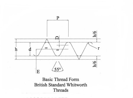
P = Pitch = 1/Number of threads per inch (tpi)
h = Angular Depth = 0.960491 x P
D = Depth of Rounding = 0.073917 x P
h/6 = Shortening = 0.160083 x P
d = Actual Depth = 0.640327 x P
r = Radius at the Crest & Root = 0.137329 x P
C = Core diameter = Major Diameter - 1.280654 x P
Effective or Pitch Diameter = Major Diameter - .640327 x P
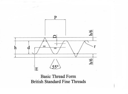
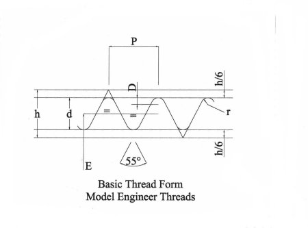

P = Pitch = 1/Number of threads per inch (tpi)
h = Triangular height = 1.1363365 x P
d = Actual Depth = 0.60000 x P
t = Shortening = 0.2681688 x P
r = Radius at the Crest & Root = 0.1808346 x P
Effective or Pitch Diameter = Major Diameter - 0.6000 x P (d)
C = Core diameter = Major Diameter - 1.2000 x P (2d)
Nuts and Bolts across flats is nominally 1.75 x Major Diameter
For Model Engineering purposes nuts and bolts are obtainable
with the hexagon heads one size less across flats,
this gives a better scale effect.
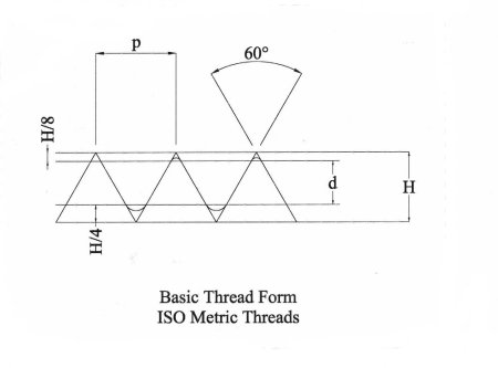
P = Pitch = 1/Number of threads per inch (tpi)
H = Angular Depth = 0.866025 x P
H/8 = Shortening of major dia = 0.108253 x P
H/4 = Shortening of minor dia = 0.216506 x P
d = Actual Depth = 0.541266 x P
r = Radius at the Root = 0.1443 x P
Hn = Basic height of
Internal Thread = 0.54127 x P
Hs = Basic height of External Thread = 0.61344 x P
Note: The form of the Metric Series of Threads varies between Internal &
External Threads, in particular the root and crest details. This allows for
flat (truncated) or radiused forms. Engineers
requiring more specific information should refer to the relevant ISO Standards.
This data base is far to small to fully cover this
subject.

P = Pitch = 1/Number of threads per inch (tpi)
H = Angular Depth = 0.866025 x P
H/8 = Shortening of major dia = 0.108253 x P
H/4 = Shortening of minor dia = 0.216506 x P
d = Actual Depth = 0.541266 x P
r = Radius at the Root = 0.1443 x P
Hn = Basic height of
Internal Thread = 0.54127 x P
Hs = Basic height of External Thread = 0.61344 x P
Society of Automobile
Engineers (SAE)

This form also occurs in the National Coarse (N.C.) and National Fine (N.F.)
series of threads.
It is very similar to the UNF and UNC threads but has a Flat Root &
Crest.
P = Pitch = 1/Number of threads per inch (tpi)
H = Theoretical Depth = 0.866 x P
D = Actual Depth = 0.6495 x P
F = Width of Flat = 0.125 x P
A = Depth of Flat = 0.108 x P
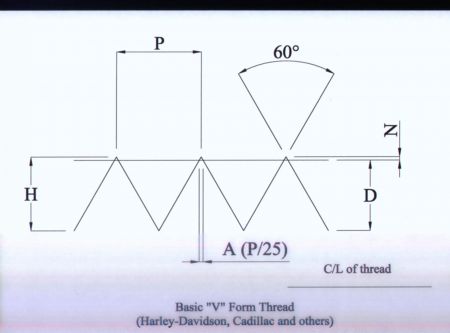
Details for this thread were taken from Machinery Handbook 9th Edition
(1938) pg 1146. This thread has been noted on older Harley Davidson Motorcycles
and is understood to have been used on older US Cadillac Automobiles.
Due to the sharp root and crest on this form, it is in theory, prone to
stress cracking. The later UNF/UNC threads should be used where possible, as
these have rounded crests and roots, thus reducing stress concentration. The
"V" thread is effectively obsolete. It still remains a very easy
thread to cut using single point tools. It is however NOT interchangeable with
modern 60 degs Imperial threads. UNF/UNC
etc. Cutting tools, Taps and Dies etc. are no longer available.
The sides of the thread form an angle of 60 degs
with each other. The top and bottom of the threads are theoretically sharp, but
in practice the crest has a slight flat equal to 1/25th x Pitch. This is
removed after the thread is cut, thus reducing the actual diameter slightly
below nominal. (D) See chart details.
P = Pitch = 1/Number of threads per inch (tpi)
H = Theoretical Depth = 0.866 x P
D = Actual Depth with Crest Relief
A= Width of Flat = P/25 (Not in the Official Standards)
N = Depth of Flat
Notes on British & International Standards
Hard copies of ISO/British Standards are very expensive, typically £30 for a
single copy. Less if you are a BSI member. Most large libraries now have
Internet Access & seem to have an agreement with the ISO/BSI. This means
that you can view any standard, but as far as I am aware, you are not able to
make copies. Thread standards are by their very nature complex documents and
unless you are working in a standards room or are a manufacturer of tooling etc.
contain large amounts of data irrelevant to model engineers work. Most of the
older non metric threads have been designated as " non-preferred
thread series " for many years. They should be avoided in new equipment
etc.
The data sheets can be downloaded as Zip files into an Excel Spreadsheet.
All files are in the protected mode. Some files have a figure in red over the tapping size. This represents the %age
full thread. This can be altered to give a tapping size to suit the thread you
require. eg. on Aluminum you may wish to tap 100% full thread. You can
also use the data to give full details of non-standard threads such as the Myford Nose etc. By entering the diameter & pitch all
the other details self calculate. No responsibility can be accepted for errors
or omissions by whatever cause.
Text © Colin Usher 2000 Illustrations
© Colin Usher 2000
All rights reserved. No part of this
publication may be reproduced, stored in a retrieval sustem,
or transmitted in any form or by any means, electronic, mechanical or
photocopying, recording or otherwise without the prior permission of the
copyright holder. Except for private & non-profit use.