Dirt Bike Suspension Setup
By Bruce Triplett
Introduction
Definitions |
| Free Length: |
The length of your spring without any load. |
| Preload: |
The length you compress the spring from it’s freeload length. |
| Race Sag: |
The extended length (measured between the swinging arm and the rear fender) minus the compressed length with the rider on the cycle. |
The most basic of the basics is having the tools needed to do the job. Get a service manual for your bike. The pro mechanics have to use them, so do you, even more so. Get a torque wrench. You do not need an expensive one - a 1/2” beam unit is perfect. Have an assortment of good hand tools: sockets, wrenches, screwdrivers, punches, hammers, hacksaw, etc. You will need a work stand to get the cycle up in the air. A ruler - I use one with inch markings because it is hard to find one with inches and metric that is over 30” long. You will need some chemicals: water proof grease, carb cleaner, WD40 or alike, chain oil, air cleaner oil, etc.
Now let’s get started with the basic suspension work - servicing the swinging arm, linkage, and shock bearings. If this stuff is not properly serviced, greased, smooth operating, and no worn parts, the best spring and valved shock will not work properly. If the bearings are rusting, frozen, or worn, you will not be able to get proper race sag, proper spring rates, or a properly adjusted shock.
Who needs to do this maintenance? If you just bought a new cycle, take it apart and do the service. The factories do not do a good job of lubing the bearings and using waterproof grease. If your present cycle has not had this service and inspection done within the last 5 months, do the service. If you recently purchased a used cycle, do the service and be prepared to buy some parts. This maintenance should be done every six months, and sooner if you use a pressure washer. A simple test is to have the cycle up on a stand so that the rear wheel is off the ground. Grab the top of the wheel, at 12 o’clock, and lift up on the wheel. If you have free play, you have wear starting. Take it apart and inspect and replace worn parts and properly service and re-torque all parts.
While you have everything apart and servicing the linkage, take the shock off. Loosen the spring up and measure the free length (length of the spring with no load) of the spring. Then reset the preload (compression of the spring from free length) on the spring to 1/2” on linkage systems and 1/4” on non-linkage systems and most Honda XR’s. If the spring is proper for your weight, the race sag (see definition above) will be within + or – 1/4” on linkage systems and 1/8” on non-linkage systems and most Honda XR’s. Also while the shock is off have it serviced if the cycle is over 9 months old or you just purchased it used. If it is a new cycle, have the nitrogen pressure recharged to factory specs.
Race Sag and Spring Rates
Now that the swing arm and linkage are all greased and free with no damaged parts we can set race sag and get proper spring rates. You guys with linkless rear suspension systems – KTM PDS, Husabergs, Canadales, ATK’s – did you do your service work as well? These bikes need service also.
To set race sag you will need a cycle stand, a ruler that can measure at least 22 inches, a hammer & a blunt punch (for turning the preload collar-- NO screwdrivers or chisels), a marking pen, approximately l5 pounds of weight, and a friend who can read a ruler. Start by putting your cycle up on the cycle stand with both wheels off the ground. Next, on the side opposite the exhaust, measure from a fixed point (I use the top of the swing arm) to a point on the rear fender that comes to a full inch measurement – i.e. 24”, 25”, etc. I am using inches because it is hard to find a long ruler with metric measurements. Place a mark with the marking pen on the swing arm and the fender where you took your measurement, show your friend these marks and write this measurement down – it will be your “extended length” reference. This is very important, so measure 2 or 3 times to make sure you are correct. All future calculations are based on this “extended length” measurement.
Now take the cycle off the stand and roll it over near a post, door, fence, or an old car. With the cycle near one of these items you will be able to sit on the cycle with both feet on the pegs and use one hand to balance by touching the support you have chosen. Now mount the cycle with the 15 pounds added. Bounce up and down several times, standing with shoulders over the handlebars. Next sit down while touching the support, with your hips over the foot pegs. Have your friend measure between the two marked points that you measured earlier. This is the “compressed length”. Subtract this from your “extended length”. This number is your race sag. Race sag should be between 3 3/4” and 4 1/4” inches (95 to 105 mm). If you set the spring at 1/2 inch preload as I suggested in the first column then you should use no more than 3 complete turns of the preload collar, in either direction, to adjust race sag. On linkless systems you should use no more than 2 turns in either direction to adjust race sag. If you have to turn the preload collars more than these amounts, you need a different spring: i.e. if you had to loosen up, you need a softer spring, if you had to tighten up, a stiffer spring. Check your service manual for the proper race sag for your cycle. On WP shocks with the allen bolt in the preload collar, do not tighten more than 6 foot pounds. THEY DO BREAK.
Spring rates are very important. The same spring can’t work for a 130 pound rider and a 260 pound rider. Most 125cc bikes are set up from the factory for about a 150 pound rider, and most 250cc bikes are set up for about a 180 pound rider. A spring has about a 20 pound rider weight range. Each 10 pounds over or under the standard rider weight requires an increase or decrease of one step (.2 kg) in spring rate: i.e. 4.8 kg to 5.0 kg or 4.8kg to 4.6 kg. You cannot substitute increasing or decreasing preload for the proper spring rate. In linkless systems, the spring is good for a rider weight range of about 10 pounds. A soft spring will require too much preload making the suspension system harsh on small bumps. It WILL NOT increase bottoming resistance. Only a stiffer spring will increase bottoming resistance. Also, a stiffer spring will make the shock less harsh on the small bumps. If a spring is too stiff, the shock will not use full travel and you will have an excess of free sag. Free sag is the sag of just the cycle with no rider (from 1” to 1 1/4” for linked and 1 3/8” to 1 5/8” for linkless systems). Improper spring rates will ruin an otherwise properly valved rear suspension. Get the right spring – it will be money very wisely spent.
I will finish up with a short discussion of linkless systems. Because a linkless system uses springs that are 75% to 100% stiffer than a link type system, preloads, free sag, and spring ranges become more critical than on the linked systems. Because the springs are so stiff – i.e. an 180 pound rider on a KTM 250 (linkless) would use about an 8.8 kg spring and a Kawasaki KX250 (linked system) rider would use a 5.0 kg spring – you need to run a lot less preload: 1/8” to 3/8” compared to l/4” to 3/4” for a linked system. If you would run too soft a spring and run more preload, the rear end would be very harsh in the first l/3 of travel. Also because of the stiffer springs used on the linkless systems, free sag will be more than on a linked system – 1 3/8” to 1 5/8” on linkless compared to 1” to 1 1/4” for the linked system. Your spring range does not cover as much of a rider weight range, approximately 10 pounds, before the spring needs to be changed.
Front Suspension
Most of this article will be basic, but I will cover a few points that you normally will not see or be told about anywhere else. We will start with some basic maintenance. Get out your service manual. The manual will give you the bolts and nuts of how to do the basic tear down. Before you start, measure the height of the fork tube that is above the top of the upper triple clamp and write this measurement down.
If you have a new bike, have the fork oil height checked and have any corrections made if needed. If you just bought a used cycle, get a suspension shop to service the forks and replace the seals and wipers. If you have a cycle that has over 5 months riding time on it, have a shop service the forks. Set the clickers to stock settings. Basic fork oil change should be performed at least every 6 months.
Next, remove the upper and lower triple clamps and inspect the upper and lower bearings and races for wear or pitting. Grease and reinstall, or replace, depending on condition. This service should be performed when you first get the cycle and once a year thereafter. Reinstall the triple clamps and adjust the tension on the bearings. Check your service manual for the proper tension.
This next step is VERY IMPORTANT. This is the PROPER WAY to install forks. ATTENTION – if improperly installed, the forks can’t work to their full potential. First install the left fork (left is determined as if you were sitting on the bike) into the triple clamps. (A little WD 40 sprayed on the fork tubes will make them slide in easier.) The measurement you took before you removed the forks will allow you to reinstall the left fork at the proper height. VERY IMPORTANT – Torque the pinch bolts to factory specs. Next, install the right fork in the triple clamp at approximately the same height as the left fork and LIGHTLY tighten ONLY ONE of the pinch bolts. This next step is CRITICAL –install the axle into the forks, grab the axle between the left and right fork, and begin rotating the axle. As you rotate the axle, loosen the pinch bolt on the right fork and move the right fork up and down until you locate the place where the axle turns most freely. Now, at this position, torque the pinch bolts to factory specs. Install the wheel and brakes, and tighten the axle and/or axle nut. Torque the axle pinch bolts on the LEFT FORK ONLY. Now, you need to work the forks up and down. The best way is to tie the cycle down in/on your trailer, or ride the cycle SLOWLY up and down the driveway, and pump the front brake level several times, making the forks move deep into the travel. Now you can TORQUE the RIGHT axle pinch bolts.
The last step for the forks is to check race sag. Most manuals and articles never mention front race sag, but it is important. With the cycle on a stand and the wheels off the ground, wrap a piece of duct tape around the brake hose such that the top of the duct tape is even with the bottom of the brake hose guide. Take the cycle off the stand, mount the cycle, and bounce up and down while you hold the front brake. Then sit down with your shoulders over the handlebars and your hips over the foot pegs. Now, look at the tape on the brake hose. The bottom of the tape should be between the bottom and the top of the guide. In this position, you will have the recommended race sag of 2 to 2 1/2 inches. If the tape is not between the top and bottom of the guide, changes need to be made. If the bottom of the tape is above the top of the guide, you need heavier springs. If the bottom of the tape is below the bottom of the guide, you need softer springs.
Within the three columns we have now covered the front and back of the cycle. Everything should have been serviced, and you should have good bearings, proper springs, sags properly set, and fresh oil. Next we will learn how to adjust the suspension to make what you have work the best it can for you.
Adjusting Suspension
You should now have the rear of the cycle serviced with good bearings, proper spring, correct sag, and good oil and nitrogen pressure in the shock. The forks should have good oil, proper oil height, and proper springs and race sag. This article will deal with learning how to adjust the forks and shock to achieve the base settings for your riding style.
To start, you need a little knowledge of how the adjusters work. When you turn the clickers you are allowing a portion of the oil to bypass the valving mechanism. This will either stiffen or soften the dampening depending on the direction you turn the clickers. With most clickers, turning the screw clockwise will stiffen the action and turning the screw counter-clockwise will soften the action. If you have a KTM 1998-2001 with a black knob on the shock compression adjuster it will work just the opposite: clockwise softens the action, counter-clockwise stiffens the action.
The clickers located on the rear shock work as follows: the clicker on the top of the shock (as installed on the cycle) is the compression adjuster. The clicker at the base of the shock is the rebound adjuster. On the forks, the clickers on the top are the rebound adjusters and at the base of the fork are the compression adjusters. But on Showa twin chamber forks (found on Suzuki 125’s from 1993 to present, Suzuki 250’s from 1993 through 2000, and Honda 250’s and 450F’s from 1997 to present), the clickers are reversed. At the top of the fork is compression and at the base of the fork is rebound. If a shock has only one adjuster, normally it will be rebound. If a fork has only one adjuster, normally it will be compression.
The next points are very important when you start to adjust the clickers. First and VERY IMPORTANT – ALWAYS START WITH REBOUND. Rebound dampening is where your control comes from. If rebound is too hard (slow) it will Pack (not return fully) causing the suspension to be harsh – therefore fooling you into thinking the compression dampening is too stiff. If the rebound is too soft (fast) it will pogo (bouncing around) this time causing someone not experienced in suspension tuning to think the compression dampening is the problem. The next step is to turn the clicker clockwise until seated, then turn counter–clockwise, counting the number of clicks. Then, using a magic marker, write your base settings on the fork and shock for both compression and rebound-i.e. 12C -- 10R. You can either use the factory original settings or, if units have been worked on by suspension tuners, their recommendations, or the middle adjustable range if you do not have a recommended setting. The next step is to use a short practice trail – 1/2 mile long or less – with a variety of different types and sizes of bumps. You do not want a long trail. You need a short trail that can be ridden a lot of times so that the computer under your helmet can average out what your suspension is doing. You can’t do this on a long trail.
Now for the fun part: Start the cycle and, with screwdriver on hand, head out to the practice trail. Wear full riding gear, have race sag properly set, proper spring rates, and the clicker positions written on the suspension units. 0Start riding your practice trail as close to race speed as possible for about 10 minutes so that you can get a good feel for how the suspension is working with these base settings. Now you are going to screw up the suspension on purpose to get a feel for how it reacts when one of the adjusters is improperly adjusted. This is called CONTROLLED SCREW-UP. Start with the rebound adjuster on the suspension unit that felt the worst to you (remember, you ALWAYS start with rebound), turning it clockwise 6 clicks (harder or slower). Now the unit will tend to pack. Remember, if you are adjusting forks, you normally have a rebound adjuster on each fork – be sure to turn both an equal amount. Now start riding, slower at first, and as you get a feel for how the improperly adjusted unit is reacting, try picking up the pace to get the feel of a packing suspension unit. After about 10 minutes, stop riding and make a mental note of how the unit worked compared to how it worked at your base setting. Now turn the rebound clicker back to it’s base setting (6 clicks counter-clockwise) and then turn it another 6 clicks counter clockwise so that the suspension unit will be softer or faster and will tend to pogo. Again start riding slowly and build speed as you feel comfortable. After about 10 minutes, stop riding and judge how the suspension unit felt in the 3 different settings. Now turn the rebound clicker 2 clicks clockwise and start riding. Hopefully this will feel a little better than your last ride. After a period of time, stop and adjust another 2 clicks clockwise and ride. Keep doing this, 2 clicks at a time, until the quality of ride begins to get worse. Then, turn the rebound clicker 1 click counter clockwise and ride, continuing to adjust 1 click at a time until you find your NEW base setting. You now have the rebound on the suspension unit (i.e. fork or shock) that you started with adjusted for the best setting for you. Write this setting down on the suspension unit.
Now do the same procedure with the compression adjuster or adjusters: six clicks stiffer than base, 6 clicks softer than base, then 2 clicks at a time toward stiffer until it gets too stiff, then 1 click toward softer until you reach the ideal setting. Do the same for the other end of the cycle. Now you have both ends adjusted for your practice trail and you have experienced poorly adjusted suspension units. When you ride or race somewhere else the computer under your helmet will be able to help you get things tuned in very quickly. Remember – write down these NEW base settings on the suspension units and in a race log. This will help you get things set up right when you go back to a previously ridden course.
A FEW TIPS. From the base settings that you have tuned for yourself: For Sand runs, adjust to stiffen compression and slow rebound. For Rocks, Roots, and Potholes, adjust to soften compression, slow rebound. For Mud, adjust to stiffen compression, speed up rebound. If your shock has a high speed compression adjuster, it does not have clicks. Therefore, you will need to adjust by PARTS OF A TURN from full stiff (clockwise) turning out – i.e.: 1 turn, 1 5/8 turns, etc. Work on tuning this adjuster just as you would the screw clickers. Remember: Always start with rebound adjustment and, if in doubt as to which adjuster is off, always do rebound. The rebound adjustment is the most important but the hardest to determine if it is right or wrong. By doing rebound first you will not get fooled into thinking the problem is compression.
All About Springs
To start with, a spring is just a steel bar with a very good memory, coiled up to form the spring shape. Just like a steel bar, the larger the bar is in diameter the stronger it will be. Also, like a steel bar, the longer the bar is the weaker the spring will be. A good example of this can be found if you compare the diameter of the spring wire and the length of that wire on the typical Japanese rear shock to the diameter of the spring wire and the length of that wire on the KTM PDS shock springs. The KTM PDS spring wire is shorter and much larger in diameter. For a 180 pound rider, a typical KTM PDS spring would be approximately 8.6 kgs/square cm to approximately 5.0 kgs/square cm for that of a Japanese bike. For those of you who prefer American measurements to the metric measurements, 8.6 kgs/square cm = 480 lbs/square inch, and 5.0 kgs/square cm = 280 lbs/square inch, almost 60% stiffer. To convert kgs/square cm to lbs/square inch, multiply the kilograms by 55.88 (5.0 times 55.88 = 280). Springs are primarily sold using the kilograms per square centimeter notation.
What do the measurements of 5.0 kgs/square cm or 280 lbs/square inch actually mean? Springs are rated by how much pressure, in pounds or kilograms, is required to compress the spring l inch or 25 mm (l centimeter). A pressure of 280 pounds is required to compress a 280 lbs/square inch spring one inch. Each additional inch of compression requires an additional 280 pounds pressure. The average rear shock compresses approximately 3 inches to get approximately 12 inches of rear wheel travel. It would take approximately 840 pounds to compress that spring three inches. It would take 1440 pounds to compress a 480 lbs/square inch PDS spring three inches.
Fork springs are rated the same way as shock springs, except they are much softer. The average fork springs for a 180 pound rider would be .42 kgs/square cm or 23.5 lbs/square inch times 2 because you have two fork springs. So, in reality, it would be the equivalent of having a single .84 kgs/square cm or 47 lbs/square inch spring in the front. Much lighter than the rear spring. The front forks typically have 12 inches of travel. To bottom front forks equipped with a pair of 23.5 lbs/square inch springs would require 282 lbs/square inch of force per fork leg for a total of 564 lbs/square inch.
The difference between a 5.0 kgs/square cm (280 lbs/square inch) and a 5.2 kgs/square cm (290 lbs/square inch) shock spring is 10 lbs/square inch. The difference between a .42 kgs/square cm (23.5 lbs/square inch) and a .44 kgs/square cm (24.5 lbs/square inch) fork spring is l lb/square inch times 2 = 2 lbs/square inch. A general rule is that a change of .2 kgs/square cm for a shock spring and .02 kgs/square cm for fork springs is needed for every 20 pounds variation from normal rider weight.
All About Preload
I am back to discuss the preload on a spring, and what effect it has on your suspension. As I stated in my last article, a spring is simply a coiled wire with a very good memory. In the last article I used 5.0 kg/sq cm and 8.8 kg/sq cm springs as examples. I will continue using these two sizes in this column.
First, we need to understand that a spring that is not compressed (i.e., is at its free length) will have only potential energy. Only when compressed will the spring have stored energy. The preload on a spring is the compressing of that spring a certain amount so that the spring is storing a specific amount of energy. The reason a spring is preloaded is to achieve the proper race sag, which is a secondary preload that occurs when you sit on the bike. The spring has a memory. It wants to be lazy, and it is always pushing back, trying to get to its free length. That 5.0 kg/sq cm (280 lb/sq in) spring, if preloaded 1 inch, would be storing 280 pounds of energy, trying to push back to its free length. Likewise, that 8.8 kg/sq cm (492 lb/sq in) spring, with the same 1 inch preload, would have 492 pounds of stored energy.
In a link type system, the ideal preload is l/2 inch, the maximum preload is 3/4 inch, and the minimum preload is 1/4 inch. If a bike equipped with a 280 lb/sq inch spring has 3/4 inch preload, you will have the equivalent of 210 pounds stored energy. If it has 1/2 inch preload, you will have the equivalent of 140 pounds stored energy, and if it has only 1/4 inch preload, you will have the equivalent of 70 pounds of stored energy.
In a PDS (KTM) system, the ideal preload is 1/4 inch, the maximum preload is 3/8 inch, and the minimum preload is 1/8 inch. If a bike equipped with a 492 lb/sq inch spring has 1/4 inch preload, you will have the equivalent of 123 pounds of stored energy. If it has 3/8 inch preload, you will have the equivalent of 185 pounds of stored energy, and if it has 1/8 inch preload, you will have the equivalent of 62 pounds of stored energy. As you can see, as the preload is increased, the stored energy increases also.
What does all this mean? Lets say your bike (link system, not PDS) is equipped with a 280 lb/sq inch spring and you had to turn the preload up to 3/4 inch to achieve proper race sag, you would now have 210 pounds of stored energy. If you would install instead a 290 lb/sq inch spring and were able to drop the preload to 1/2 inch, you would now have145 pounds of stored energy. That 290 lb/sq inch spring, preloaded to 1/2 inch, would require less force to begin movement of the rear of the bike (i.e., on a smaller bump), than would the 280 lb/sq inch spring preloaded to 3/4 inch. That 290 lb/sq inch spring would require 870 pounds of force to bottom (3 inch shock travel) compared to 840 pounds of force for the 280 lb/sq inch spring. So the heavier spring (the correct spring in this example because it achieves the proper race sag) is more progressive than the spring that was only one step too light. The correct spring will move over the small bumps better and resist bottoming better. If you require more than one step difference in spring rate, the results be much more dramatic.
The PDS (KTM) springs become more critical since they have heavier spring rates than suspensions with link systems. Lets say you should be using an 8.8 kg/sq cm (492 lb/sq inch) spring but you are using an 8.4 kg/sq cm (470 lb/sq inch) spring (PDS springs normally come in .4 kg/sq cm or 22 lb/sq inch increments). If you had to preload the 8.4 kg/sq cm (470 lb/sq inch) spring1/2 inch (235 pounds stored energy) in order to achieve the proper race sag, but the correct spring 8.8 kg/sq cm (492 lb/sq inch) would have required a preload of 1/4 inch (123 pounds stored energy), the 492 lb/sq inch spring would make the shock much more efficient on small bumps. It would also resist bottoming much better, since the 492 lb/sq inch spring would require 1476 pounds to bottom while the 470 lb/sq inch spring would bottom with only 1410 pounds.
Now lets examine the influence of race sag (the secondary preload). Most race sags should be 4 inches (+ or – 1/4 inch). This will add 1 inch additional preload on the spring before you hit the first bump. Add this additional stored energy to the examples above and you will see the large increase in overall stored energy. By adding another 280 pounds of stored energy (created by the one inch additional preload due to the race sag) to the 280 lb/sq inch spring that is preloaded 3/4 inch (210 pounds stored energy) you would have a total of 490 pounds of stored energy. By adding another 290 pounds of stored energy to the 290 lb/sq inch spring that is preloaded 1/2 inch (145 pounds stored energy) you would have 435 pounds of stored energy. By adding another 470 pounds of stored energy to the 470 lb/sq inch PDS spring that is preloaded 1/2 inch (235 pounds stored energy), you would have a total of 705 pounds of stored energy. By adding another 492 pounds of stored energy to the 492 lb/sq inch spring that is preloaded 1/4 inch (123 pounds stored energy), you would have a total of 615 pounds of stored energy. Remember, you must have a force at the rear wheel greater than the total stored energy of the preload and the secondary preload to just make the shock move at all, even as little as 1/16 of an inch.
OK. So lets suppose you decide that you won’t spend your money on a new spring, and will just run more race sag and less preload to make the suspension work easier. WRONG. The amount of stored energy you are going to reduce by backing off the preload will be more than offset by the additional secondary stored energy that will be added by increasing race sag. So, if you run too much race sag, the secondary preload goes way up and the suspension will become harsher on the small bumps. In addition, the rising rate linkage that the shock is hooked to (or the tapered needle inside on a PDS shock) will be in the harder part of its travel. I hope I have convinced you to use the right spring, which will guarantee a smoother ride. I have used the rear spring in this article, but the front suspension works the same way, only using lighter springs.
Shock Hydraulics
This month I will describe how a shock works hydraulically. The hydraulic shock is just a pump. However, the fluid does not get pumped out like it does in a normal pump. Rather, the fluid is only pumped from one chamber to another. Since fluid does not compress, the shock or fork must have someplace to pump the fluid (oil). Because the oil has body, or viscosity, it will cause a resistance to the pump, slowing it down. By knowing these few facts we can start to understand how a hydraulic shock works.
Early shocks had a shock body, a separate cylinder, and a shaft with a piston that traveled in the separate cylinder. The cylinder was inside the body, and the shaft and piston were inside the cylinder – with some oil and air filling the shock body and a cap covering the top of the body to contain all the parts. As the piston moved up and down in the cylinder it would pump the oil out of the cylinder into the space between the outside of the cylinder and the inside of the shock body. Since the shock was not completely filled with the oil - some of the space inside the shock was left with only air - the oil could be pumped in and out of the cylinder. The problem with this type of shock design was that the air would mix with the oil causing the oil to become thinner, therefore losing dampening control. Also, air contains impurities (just look at an engine air filter sometime) which will cause the air to heat up. This would cause a change in internal pressures in the shock and cause dampening forces to change.
Today’s shocks have a shock body, a shaft and piston, and a chamber attached to the body – either directly or with a hose. The purpose of this chamber (reservoir) is to give the oil a place to be pumped as the shock goes through its travel. In the reservoir there is a separator – either a bladder or a free piston – that separates the oil from the air space so the oil and air do not mix. With no air to mix with the oil, the oil viscosity does not thin out, hence a more consistent dampening. On the other side of the separator is pressurized nitrogen instead of air. Nitrogen is cleaner and heat does not affect nitrogen as much as it affects air, so the pressure stays more consistent, creating a more consistent dampening force.
As the piston goes down in the shock body (on the compression stroke) some of the oil is forced into the reservoir, while most of the oil passes through a series of holes in the piston and ends up on the top side of the piston. The act of the oil passing through these holes slows down the speed of the compression stroke.
As the load is taken off the shock, the spring then tries to return the shock (on its rebound stroke) to its fully extended length. When the shock starts rebounding, the oil in the reservoir is sucked back into the shock body. The oil that passed through the piston is now compressed between the top of the shock body and the piston. The oil then passes through another series of holes, slowing the rebound. This oil and the oil from the reservoir mix together so the process can be repeated again and again. The nitrogen pressure helps push the oil back into the shock body, so the shock body always remains full of oil.
Basically, the front forks (cartridge variety) work just like the old style shocks with the separate cylinder (cartridge) inside the fork tubes. The only difference is that the modern fork is much larger and therefore holds a lot more oil.
The Valve Stack
I will describe how the valve stack works within a hydraulic damper – i.e. - fork, or shock. In this discussion I will only be dealing with the speed or pressure sensitive type system, not the position sensitive type system.
As I explained in my last column, the damper unit is a closed system which utilizes a chamber or air space through which the oil is circulated. A piston is mounted on a shaft or rod that travels in a cylinder – i.e - shock body or cartridge tube. The piston is actually a disc with holes machined into the top continuing through the bottom, in a special pattern such that some are machined more deeply than others, allowing two actual levels of holes on each surface – one set acting as exit holes and one set acting as entrance holes. The entrance holes are the recessed holes of each surface while the corresponding exit holes on the opposite surface are flush. To control the restriction of oil through these holes, thin spring steel shim washers, when stacked on each surface of the piston, cover only the exit holes on each side. The recessed entrance holes allow oil to pass through the piston, compressing the oil against the end of the damper unit and the shim stack on the exit surface of the piston. This creates pressure on the shim stack. The shim stack on the top of the piston controls the compression dampening while the shim stack on the bottom of the piston controls the rebound dampening. As the piston moves in the damper, the pressure increases and will become great enough to flex the outer edges of the shim stack, allowing oil to begin to flow into the opposite chamber in the damper unit. The amount of flexing of these shims controls the resistance of the oil flow, thereby slowing or increasing the damper’s movement. As the speed of the piston increases, the volume of the oil being pumped is increased and therefore the pressure exerted against the shim stacks is also increased, causing the shims to flex more. (Smaller bumps create less piston speed, therefore creating less resistance, while larger bumps create greater piston speed, therefore creating more resistance.)
As I stated earlier, shims are thin spring steel washers. They will be stacked up in pyramid fashion, with the largest diameter shim against the piston surface, and decreasing in diameter as the stack height increases. More shims, thicker shims, smaller diameter shims create more resistance, while less shims, thinner shims, larger diameter shims create less resistance. A GOOD suspension tuner can adjust or control the amount of flexing of the shim stack by varying the thickness, the diameter, and the amount of the shims used in the stack. Usually the REAR SHOCK will contain shims varying in size from 22mm in diameter to 40mm in diameter, and the thickness will vary from .1mm to .3mm. FORK shims are much smaller, usually varying from 10mm to 24mm in diameter and from .1mm to .15mm in thickness.
The ADJUSTMENT SYSTEM usually consists of a hole drilled through the damper unit SHAFT entering the shaft below the piston and exiting the shaft through cross drilled holes located above the piston, serving as a bypass of the shim stacks. If this bypass passage was not controlled in some way, the shim stack would not offer as much restriction of the oil flow because some of the oil would be allowed to flow around the piston and shim stack. Therefore, a tapered adjustment screw is added to control the amount of oil bypassing the shim stack. When this tapered screw is turned clockwise, the bypass passage is closed down, allowing less oil to bypass the shim stack and therefore more oil to be forced through the shim stack, thereby creating more restriction - resulting in harder suspension. When the screw is turned counterclockwise, the bypass passage is opened up, allowing more oil to bypass the shim stack and therefore less oil to be forced through the shim stack, thereby creating less restriction - resulting in softer suspension.
Most FORKS actually have a separate rebound piston and shim stack and a separate compression piston and shim stack. The compression piston in the fork does not move. It is usually referred to as a base valve because it is mounted in the base or bottom of the fork. The rebound piston does all the work. It moves up and down in the cartridge tube, forcing the oil through the compression (base valve) piston and valve stack and then sucking the oil back into the cartridge tube and rebound stack for rebound restriction i.e. - dampening. Each of these pistons has a spring-loaded one-way shim on the opposite piston surface from the actual shim stack. This one-way shim will lift so as not to restrict the oil flow in one direction and will close allowing restriction or dampening in the opposite direction. This feature allows the two pistons, compression and rebound, to work independently of each other, and keeps the cartridge full of oil and ready for the next cycle.
03/04 KTM Whitepower Setup
I need to discuss a change on the 2003 and 2004 KTM (White Power) shock sag set up. White Power made a change in these shocks. They installed a 12mm long top-out spring inside the shock. Because of this change, the proper race sag should be between 112 and 118 mm. If you try to use the 100mm normal race sag, you will start compressing the top-out spring. Since the spring can’t be compressed to zero, you can’t use the same race sag measurement as on the older bikes. The factory directions still incorrectly recommend the 100mm race sag setting.
KTM PDS Shock
In the last column I discussed how a speed/pressure sensitive dampening system works, and I said I would explain how a KTM PDS shock works in this column. However, we must first define a position sensitive system.
A position sensitive system controls dampening by how far the damper (in forks OR shock) travels, not by its speed/pressure. The most common type of position sensitive dampening system is still used in the forks of most road bikes and low budget trail bikes. In these bikes, the inner fork tube (usually the upper tube which is chrome plated) encases a smaller tube called a dampening rod that is bolted into the lower fork leg. The dampening rod’s upper end is enlarged and has a nylon ring around it so that it can slide up and down inside the upper tube, much like a piston in a cylinder. This dampening rod has a series of holes drilled crosswise along its length. These holes will close off as the dampening rod travels up into the upper tube. The more the fork is compressed the more holes are closed off, restricting the amount of oil forced out of the dampening rod, and thereby stiffening the dampening. In theory, the fork is compressed more on big bumps than on little bumps so that the fork stiffens as it gets deeper into the travel. As the fork rebounds, the holes are uncovered - allowing less dampening. One of the main problems with this system is that the rebound circuit provides very little rebound dampening.
 Now that you have a basic understanding of a position sensitive system I will explain how it applies to the KTM PDS shock. The KTM (White Power) shock does not use a dampening tube with holes. Instead, they utilize a very large tapered needle, much like the needle in a carburetor – only much larger. This needle is mounted at the bottom of the shock body. The center of the shock shaft is machined so that as the shock compresses the needle will enter the shaft and slow the flow of oil up through this passage. The passage is crossed-drilled above the first piston, much like in the rebound adjustment system used on most shocks. The only difference is that since there is no external adjuster screw, the oil flow is controlled by the stroke depth of the shock.
Now to complicate the matter a little more, White Power added a second piston above the cross-drilled shaft. When the shock travels only a small amount, the oil flows up through the center of the shaft, exiting the cross drilled holes - therefore missing the first piston completely. Oil is now between the two pistons. As the pressure increases the shims on the second piston will start to flex, allowing the oil to pass through the piston in the process I discussed in my last column. As the shock continues to compress deeper into the travel the needle enters the hole in the shaft thereby restricting the amount of oil that is bypassing the first piston. When the pressure increases enough it will cause the shims on the first piston to flex, thereby allowing oil to pass through the first piston and then on through the second piston (since the shims on that piston are already open.) The first piston is used in the deeper part of the shock travel and is valved stiffer than the second piston. The second piston is used in the early part of the shock travel and is valved lighter. This shock still has the rebound bypass adjustment system above the second piston, which works just like a standard shock.
The PDS shock works with a combination of the speed/pressure sensitive and the position sensitive systems. The reason for using both systems in the shock is that the late model KTM’S (1998 to present) do not have a complicated link system hooked to the shock. KTM needed to use the position sensitive system to hydraulically make the shock stiffer so that it would not bottom easily and could be valved such that it would be ridable. The link system is also a type of position sensitive system. As the links travel through its arc, compressing the shock, it makes the shock stiffer through mechanical advantage.
The front forks created by my own Terrain Tamer modification and some of the front forks made by Marzocchi utilize both the speed/pressure sensitive and position sensitive systems for the compression dampening function while the rebound dampening function is strictly controlled by the speed/pressure sensitive system. This combination allows very plush dampening in the first part of the fork travel but stiffer dampening in the deeper part of the travel, which very effectively controls bottoming resistance.
Helpful Tools
In this column and the next I will describe three tools that you can make that will simplify checking and setting race sag on the rear shock.
First I will describe how to make and use a sag stick. Basically, you will be making a customized ruler to be used for your specific bike. You will need a piece of aluminum or steel 1/8 or1/4 inch thick, ½ to 1 inch wide, and approximately 28 inches long. Since bikes vary in their design around the rear axle/chain adjuster systems, you will need to choose from several options for configuring the bottom end of the sag stick.
Option 1: If your rear axle has a hole drilled in its center, you can drill a hole in the end of your sag stick the same size as the hole in the axle. Then install a bolt and nut in the hole of the sag stick with approximately ¾ to 1 inch of the bolt extending past the nut. This bolt will then fit into the hole in the axle - thereby allowing the sag stick to be supported with no up or down “slop”.
Option 2: If your axle is the type that is plugged or not drilled, then you will not be drilling a hole in the sag stick. Instead, you will need to bend the end of the sag stick at a 90 degree angle approximately ½ inch from the end. This will allow the sag stick to rest on top of the chain adjuster bolt.
Option 3: If your bike has the cam type chain adjusters, it will have a pin for the cam to push against. Just drill a hole in the end of the sag stick to fit over this pin. You may have to trim away some of the sag stick to allow the stick to extend up toward the rear fender at a 90 degree angle to the swingarm.
Now that you have the sag stick made to fit at the axle you are ready to calibrate the stick. Put the bike up on a stand so that the rear wheel is off the ground and can be turned without touching. Install the sag stick at the wheel. The top of the sag stick should be above the rear fender and at about a 90 degree angle to the top of the swingarm. Using a thin line permanent marker (such as a Sharpie), draw a horizontal line (which will be known as the extended line) on the sag stick where it intersects the bottom of the fender, and draw a vertical line on the fender along the leading edge of the sag stick.
 Remove the sag stick from the bike and place it on a work bench/table. With a metric ruler, measure down from the extended line and draw a line at the distance of your ideal race sag (100mm on link type bikes and PDS KTM’s up to 2002, 115 mm on PDS 2003 & 2004, and 110mm on 2005). This is your race sag line. You will now need to draw two more lines – one 5mm above the race sag line and one 5mm below the race sag line. Then measure down from the extended line and draw a line for static sag (30mm for link systems, 35mm for PDS up to 2002, 40mm for PDS 2003-2005). To finish, draw two more lines – one 5mm above and one 5mm below this static sag line.
 These 5mm above and below lines give you the maximum and minimum range of adjustment for both race sag and static sag.
Now, when you want to measure or adjust your race sag, put the bike up on a stand and check your extended length. It should always be the same unless you have bent your subframe or have tight or worn linkage/swingarm bearings. (If bearings are tight, the extended length will probably be too short and if bearings are loose or worn, the extended length will probably be too long.) Remove the bike from the stand, bounce it up and down and sit on the bike in the attack position and have an assistant install the sag stick at the wheel. Line up the vertical line on the fender with the leading edge of the stick. Have the assistant draw a pencil line on the sag stick where the bottom edge of the fender intersects the stick. Park the bike and measure down from your extended line to the pencil line. This is your race sag. Now, check your static sag. With the bike on the ground, push up and down on the rear fender and allow the suspension to settle. Install the sag stick and draw a pencil line where the bottom of the fender and the stick intersect. This is your static sag. If you have the proper spring for your weight, the race sag will be between the lines you created that were 5mm above and 5mm below your race sag line, and the static sag will be between the lines you created 5mm above and 5mm below your static sag line. If your measurement is ABOVE the 5mm line you made above the race sag line, the spring is too stiff (indicating a need for less preload or a softer spring.) Adjust preload to get proper race sag and check static sag. If static sag is proper, the spring is O.K. If race sag is BELOW the 5mm line you made below the race sag line the spring is too soft (indicating a need for more preload or a stiffer spring.) Adjust preload to get proper race sag and check static sag. If static sag is O.K, your spring rate is correct. A general rule of thumb: Once race sag is correct, if you have too much static sag this indicates that the spring is too stiff. If you have too little static sag this indicates that the spring is too soft. For reference, 1mm of preload is approximately 2mm of race sag.
Remember to always use proper safety precautions and equipment including eye protection when drilling or cutting metal.
More Tools
This is my second column concerning simple tools you can make to simplify checking and adjusting race sag on the rear shock. In my last column I described in detail the procedure used to create a sag stick, which, once completed, is extremely useful for checking and setting race sag. Today I will describe two more tools which are mainly used for adjusting race sag.
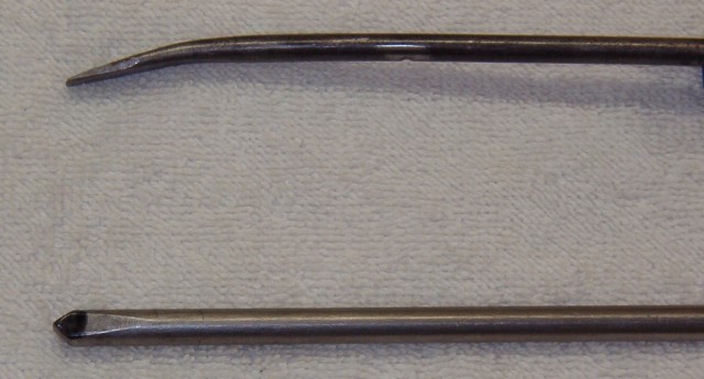 The first of these two tools is a punch you can use to loosen the preload adjuster rings. It can also be used to turn the adjuster rings. You will need a piece of 5/16 inch round or square steel rod approximately 12 inches long. On one end, cut or grind two flats at 45 degree angles to the length of the rod such that they form a 90 degree point in the center of the end of the rod. This end will fit into the notches in the adjuster rings such that when the rod is struck with a hammer it will turn the ring without digging into the notches. It works much better than a screwdriver or a chisel.
The final tool is made from a screwdriver. It will serve as a pry bar to turn the adjuster rings, but it is NOT to be hit or struck. You need a flat blade screwdriver with a 1/4 to 5/16 inch rod shaft approximately 8 to 10 inches long. Clamp the screwdriver end in a vise, flat sides against the jaws, at approximately 1 to 1 ½ inches from the end. Put a slight bend in the shaft. You will use this as a pry bar between the reservoir and/or frame tube and the end in the notches of the adjuster rings. Then you can just pry the adjuster rings around to adjust preload. You may have to play with the length and amount of bend you need, depending upon your make of bike. Each make, model, and year has different space requirements.
Mark these three tools and keep them together. The next time your weight changes (maybe every two weeks?) you will have the right tools to both check and adjust race sag.
For a detailed description of sag settings, refer to my second column Race Sag and Spring Rates.
Remember to always use proper safety precautions and equipment including eye protection when drilling or cutting metal.
Turning
Hi. I am back after some time off. This column will deal with a question that is most frequently asked: why doesn’t my bike turn well?
The answer is not simple because you may be experiencing one of two different problems, with multiple potential cures for each.
First let’s say your turning problem is that the bike doesn’t turn tight enough – i.e.- it runs wide in a turn (I refer to this as understeering). Here are some possible problems and solutions
- The front forks may be too long, causing the rake – i.e. the angle of the forks – to be too far from vertical. This can be caused by the fork being too far down in the triple clamps, or by fork springs that are too stiff.
-
Fork compression dampening may be too stiff or rebound fork dampening may be too fast or soft, which can cause too much fork rake.
-
Too much rear shock race sag or too soft of a rear shock spring can cause too much fork rake.
-
Rear shock compression dampening could be too soft or rebound dampening too slow or hard, which can cause too much fork rake.
-
Tire selection could also contribute to the problem – a too soft compound tire on a hard ground track. Different tires, makes, and/or styles may affect the handling.
- Riding style can cause the bike to run wide – i.e. a rider sitting too far back on the bike, not powering through a turn, pulling in the clutch, or having a foot touching the ground. During a ride, you can’t correct a bike’s setup problem or a tire problem, but you can make adjustments in your riding style. Possible changes include moving further forward on the bike and/or getting on the gas to get the back wheel to step out farther than the front wheel (making the front of the bike turn tighter).
The second problem may be that the front end turns too tight – i.e. tucks in (I refer to this as oversteering). Here are some possible problems and solutions:
- The front forks may be too short, causing the fork rake to be too steep from vertical. This can be caused by the fork being too far above the top triple clamp, or by fork springs that are too soft.
- The fork compression dampening may be too soft or the fork rebound dampening too slow or hard, which can cause the fork rake to be too steep.
- There may not be enough rear shock race sag. If your rear spring is too stiff, if your shock compression dampening is too stiff, or if your rebound dampening is too fast or soft, the back end will be too high, causing the fork rake to be too steep.
- Incorrect tire selection or tire pressure that is too low can cause the front end to knife or tuck in a turn.
- Rider position (too far forward) or too much throttle can also cause the front end to tuck in.
As you can see, there are many variables and I have not given you any absolute answers. You have to come up with the best compromise or balance for your situation. I have had my bike exhibit all three traits in a single day: it turned perfectly, oversteered, and understeered. Therefore, I had the perfect balance for the course.
To summarize, you can’t change your setup or tires during the race, only your riding style. Since the terrain is constantly changing you will have to look ahead, size up the terrain, and make adjustments to your riding style to maximize your results. If your bike turns wide the majority of the time, or tucks the majority of the time, go back to the section covering your problem and change the setup to achieve that perfect or near perfect balance.
KTM Shock Springrates
In this column, number 13, I am going to address proper shock spring rates for KTM’S with PDS shock systems. In my column # 5 I detailed how springs work, how they are rated, and how to measure race sag and static sag. (You can access my back columns at www.brucessuspension.com.)
As a quick review: the 1998 to 2002 KTM’s should be set up with 97 to 105 mm race sag and 30 to 35mm static sag. The 2003 and 2004 KTM’s should be set up with 115 to 120 mm race sag and 40 to 45 mm static sag. The 2005 and 2006 KTM’s should be set up with 110 to 115 mm race sag and 35 to 40 mm static sag.
The following chart shows recommended spring weights based on rider weight (as wearing casual attire, not race gear.)
lbs |
125 |
200 |
250-380 |
400-450 |
500-525 |
| 140 |
7.2 |
7.4 |
7.6 |
8.0 |
8.2 |
| 150 |
7.4 |
7.6 |
7.8 |
8.2 |
8.4 |
| 160 |
7.6 |
7.8 |
8.0 |
8.4 |
8.6 |
| 170 |
7.8 |
8.0 |
8.2 |
8.6 |
8.8 |
| 180 |
8.0 |
8.2 |
8.4 |
8.8 |
9.0 |
| 190 |
8.2 |
8.4 |
8.6 |
9.0 |
9.2 |
| 200 |
8.4 |
8.6 |
8.8 |
9.2 |
9.4 |
| 210 |
8.6 |
8.8 |
9.0 |
9.4 |
9.6 |
| 220 |
8.8 |
9.0 |
9.2 |
9.6 |
9.8 |
| 230 |
9.0 |
9.2 |
9.4 |
9.8 |
10.0 |
| 240 |
9.2 |
9.4 |
9.6 |
10.0 |
10.4 |
These rates provide a good starting point for most riders. Some riders may want to deviate from these suggested rates to accommodate individual rider styles or terrain. If you race or ride mostly in sand, you probably should go to the next stiffer spring (i.e. from an 8.4 to 8.6). Conversely, if you ride a lot of rocks, you may prefer the next step softer (i.e. from an 8.4 to 8.2). “Out of the crate” KTM’s had very poor stock spring rates: the 1999 to 2003 models were fitted with a 7.1 to 9.0 progressive spring, which did not work well for ANYONE. The 2004 models got a little closer to being correct with an 8.8 spring, which was good for a 200 pound rider on a 2 stroke and a 180 pound rider on a 4 stroke. The 2005 and 2006 models were fitted with a 7.6 spring on the 2 stroke which was good for a 140 pound rider.
If you fit the rear shock with the spring of proper weight, you will feel a big improvement in performance of the back end of your KTM.
Until next time, here’s to smooth riding. SHOK DOC (Bruce Triplett)
Bruces's Suspension Service |
350 Skysail Road |
Salisbury, NC 28146 |
704-637-3675 |
|
